WEB Catalog
Product List
- Air Management System
-
Directional Control Valves
- Pilot Operated 4/5 Port Solenoid Valves
- Pilot Operated 3 Port Solenoid Valves
- Direct Operated 3/4/5 Port Solenoid Valves
- Reduced-wiring Fieldbus System (Serial Transmission System)
- Wireless System
- Air Operated Valves
- Mechanical Valves/Transmitters
- Finger Valve/Hand Valves/Residual Relief 3 Port Valve
- Blow Guns
- Power Valves
- ISO Valves
- Explosion-Proof Valves
- Pilot Operated 4/5 Port Solenoid Valves
-
Air Cylinders
- Standard Air Cylinders (Round Type)
- Standard Air Cylinders (Square Cover)
- Compact Air Cylinders
- Environment Resistant Cylinders
- Floating Joints/Rod End
- Air-hydro Units
- Mechanically Jointed Rodless Cylinders
- Magnetically Coupled Rodless Cylinders
- Table Cylinders
- Guide Cylinders
- Dual Rod Cylinders
- Lock Cylinders/Cylinder with An End Lock
- Fine Lock Cylinders
- Specialty Cylinders
- Clamp Cylinders
- Pin Shift Cylinder
- Stopper Cylinders
- Stroke Reading Cylinders
- Valve Mounted Air Cylinders
- ISO Cylinders: ISO Standards (6432)
- ISO Cylinders: ISO Standards (15552)
- ISO Cylinders: ISO Standards (21287)
- ISO Cylinders
- Shock Absorbers
- Auto Switches
- Wireless Auto Switches
- Actuator Position Sensor
- Flow Control Equipment
- Standard Air Cylinders (Round Type)
- Rotary Actuators/Air Grippers
-
Electric Actuators/Cylinders
- e-Actuator
- Manifold Controller/Manifold Controller Compatible Electric Actuator
- Battery-less Absolute Encoder Type
- Slider Type
- Rod Type/Guide Rod Type
- Slide Tables
- Miniature
- Rotary Tables
- Grippers
- Grippers for Collaborative Robots
- Controllers/Drivers
- Teaching Box
- Environment
- Motorless Type
- Mounting Kit for Multi-Axis System
- Electric Cylinders
- Card Motor
- Made to Order
- e-Actuator
-
Vacuum Equipment (Vacuum Generators/Vacuum Suction Cups/Other)
- Vacuum Ejectors (Vacuum Generators)/Vacuum Pump Systems
- Vacuum Ejectors
- Vacuum Gripper System (Foam Type)
- Vacuum Release Valve Units
- Air Suction Filters
- Vacuum Pads (Vacuum Suction Cups)
- Special Pads
- Gripper for Collaborative Robots
- Vacuum Saving Valves
- Magnet Buffer
- Vacuum Flow
- Vacuum Regulators
- Related Equipment for Vacuum Systems
- Vacuum Ejectors (Vacuum Generators)/Vacuum Pump Systems
- Grippers for Collaborative Robots
- Compact Compressor
- Air Preparation Equipment
- Modular F.R.L./Pressure Control Equipment
- Modular F.R.L. Units
- Pressure Control Equipment
- Booster Regulators
- Lubrication Equipment
- Gas Generator
- Fittings and Tubing
-
Flow Control Equipment
- Speed Controllers for General Purposes
- Speed Controllers for Low Speed Control
- Speed Controllers Special Environments
- Speed Controllers with Special Functions
- Tool Operation Type Speed Controllers
- Air Saving Speed Controllers Air Saving Valves
- Remote control valve (Electric speed controller)
- Related Equipment
- Speed Controllers for General Purposes
- Silencers/Exhaust Cleaners/Pressure Gauges
- Air Blowing Equipment
-
Switches/Sensors/Controller
- Electronic Pressure Switches/Sensors (Self-contained Type)
- Electronic Pressure Switches/Sensors (Remote Type)
- Mechanical Pressure Switches
- Electronic Flow Switches/Sensors
- Clamp-on Type Flow Sensor
- Mechanical Flow Switches
- Air Management System
- Controllers
- Electronic Temperature & Humidity Switches
- Auto Switches for Air Cylinders
- Auto Switches for Rotary Actuators and Air Grippers
- Position Sensor
- Electronic Pressure Switches/Sensors (Self-contained Type)
-
Static Neutralization Equipment
- Static Neutralization Equipment Ionizer Bar Type
- Static Neutralization Equipment Nozzle Type Ionizer
- Static Neutralization Equipment Fan Type Ionizer
- Static Neutralization Equipment Ionizer Gun
- Static Neutralization Equipment Desktop Duster Box
- Static Neutralization Equipment Electrostatic Sensor/Sensor Monitor/Meter
- Static Neutralization Equipment/Ionizers
- Static Neutralization Equipment Ionizer Bar Type
-
Industrial Device Communication Equipment/Wireless System
- Wireless System: PROFINET Compatible Products
- Wireless System: EtherNet/IP Compatible Products
- Wireless System: EtherCAT Compatible Products
- Wireless System: IO-Link Compatible Products
- Wireless System: CC-Link Compatible Products
- Wireless System: DeviceNet Compatible Products
- Industrial Device Communication Equipment: PROFINET Compatible Products
- Industrial Device Communication Equipment: EtherNet/IP Compatible Products
- Industrial Device Communication Equipment: EtherCAT Compatible Products
- Industrial Device Communication Equipment: Modbus TCP Compatible Products
- Industrial Device Communication Equipment: ETHERNET POWERLINK Compatible Products
- Industrial Device Communication Equipment: CC-Link IE Field Compatible Products
- Industrial Device Communication Equipment: SSCNET III Compatible Products
- Industrial Device Communication Equipment: MECHATROLINK-Ⅲ Compatible Products
- Industrial Device Communication Equipment: PROFIsafe Compatible Products
- Industrial Device Communication CIP Safety Compatible Products
- Industrial Device Communication Equipment: IO-Link Compatible Products
- Industrial Device Communication Equipment: PROFIBUS Compatible Products
- Industrial Device Communication Equipment: DeviceNet Compatible Products
- Industrial Device Communication Equipment: CC-Link Compatible Products
- Industrial Device Communication Equipment: AS-interface Compatible Products
- Industrial Device Communication Equipment: CompoNet Compatible Products
- Industrial Device Communication Equipment: Interbus Compatible Products
- Industrial Device Communication Equipment: MECHATROLINK-Ⅱ Compatible Products
- Other: RS232C Compatible Products
- Other: RS485 Compatible Products
- Wireless System: PROFINET Compatible Products
- Process Valves
- Chemical Liquid Valves/Fittings & Needle Valves/Tubing
- Process Pumps(Diaphragm Pumps)
-
Temperature Control Equipment
- Thermo-Chillers (Circulating Fluid Temperature Controllers) Standard Type/Basic Type
- Thermo-Chillers (Circulating Fluid Temperature Controllers) Inverter Type
- Thermo-Chillers (Circulating Fluid Temperature Controllers) Dual Channel Thermo chiller for Lasers
- Thermo-Chillers (Circulating Fluid Temperature Controllers) Rack Mount Type
- Thermo-Chillers (Circulating Fluid Temperature Controllers) High performance/Type & Inverter Type
- Chiller Compliant Regulations
- Thermo-cons/Thermoelectric Baths (Peltier-Type Temperature Control Equipment)
- Air Temperature Controllers
- Thermo-Chillers (Circulating Fluid Temperature Controllers) Standard Type/Basic Type
- Process Gas Equipment AP Tech
- High Vacuum Equipment
- Industrial Filters/Sintered Metal Elements
- Pneumatic Instrumentation Equipment
- Hydraulic Equipment
Theme
-
Clean Series/Low-Particle Generation
- Directional Control Valves
- Air Cylinders
- Rotary Actuators
- Air Grippers
- Air Dryers
- Compressed Air Cleaning Filter Series
- Clean Gas Filters/Air Filters
- Exhaust Cleaner for Clean Room/Clean Exhaust Filter
- Modular F.R./Pressure Control Equipment
- Fittings
- Tubing
- Flow Control Equipment
- Switches/Sensors
- Flow Switch
- Electric Actuators
- Directional Control Valves
- Fluoropolymer Equipment/PVC Equipment
-
Series Compatible with Secondary Batteries Series 25A-
- Air Management System
- Directional Control Valves
- Wireless System
- Actuators
- Related Products
- Rotary Actuators/Air Grippers
- Vacuum Equipment
- Air Preparation Equipment/Clean Air Filters
- ModularF.R.L./Pressure Control Equipment
- Flow Control Equipment/Fittings
- Tubings
- Detection Switches/Auto Switches
- Static Neutralization Equipment/Ionizers
- Process Valves
- Process Gas Equipment
- Electric Actuators
- Air Management System
- Copper, Fluorine-free Equipment Series 20-
- ISO Products
- Arc Welding Process Equipment
- IO-Link Compatible Products
- Grease-free Nitrogen (N2) Compatible Equipment
- List of ATEX Compliant Products
- Explosion-Proof Valves Certified Products
- Equipment for the Food Manufacturing Industry
- Equipment for the Semiconductor Industries
-
Equipment for the Semiconductor Industries (Temperature Adjustment Line)
- Thermo-Chillers (Circulating Fluid Temperature Controllers) Standard Type/Basic Type
- Thermo-Chillers (Circulating Fluid Temperature Controllers) Inverter Type
- Thermo-Chillers (Circulating Fluid Temperature Controllers) Rack Mount Type
- Thermo-Chillers (Circulating Fluid Temperature Controllers) High performance/Type & Inverter Type
- Chiller Compliant Regulations
- Thermo-cons/Thermoelectric Baths (Peltier-Type Temperature Control Equipment)
- Thermo-Chillers (Circulating Fluid Temperature Controllers) Standard Type/Basic Type
Industrial Device Communication Equipment: EtherNet/IP Compatible Products
Serial Transmission System EX600
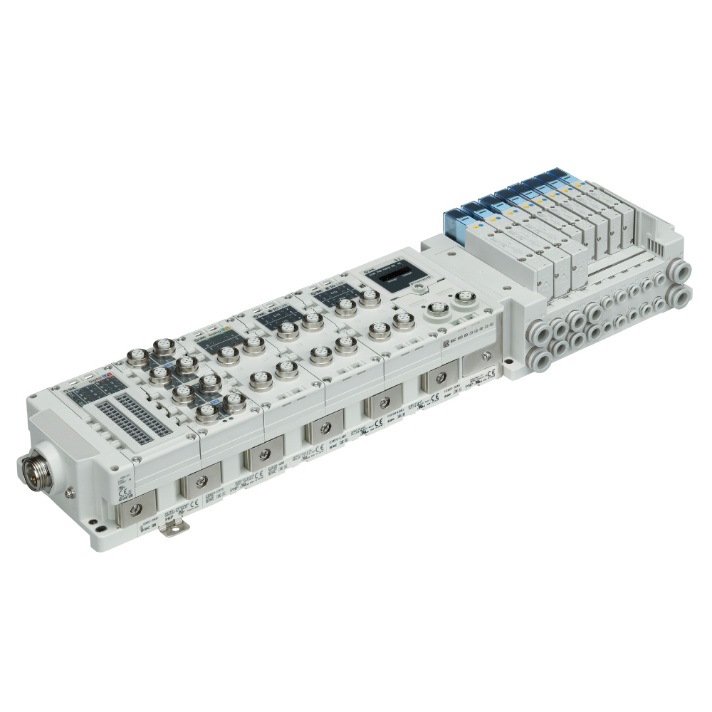
-
・For Input/Output
・IO-Link An IO-Link unit compatible terminal unit has been added. [New]
∗The applicable protocols differ depending on the series.
For details, refer to the catalog of each series.
▶IO-Link Devices
∗ The EX600-SPN1/SPN2 series will be discontinued in October 2023.
Please select the EX600-SPN3/SPN4 series.
-
2D/3D CAD
The new SMC CAD SYSTEM, CADENAS, allows you to output 2D/3D CAD data with full part numbers in various data formats. Responses to part number selection has been greatly improved with the newly developed system.
Click here for 2D/3D CAD2D CAD
Click here for 2D CAD Serial Transmission System EX600
Manual
Series View search result EX600 View search result Serial Transmission System EX600
DoC/IM
Series View search result EX600 View search result
Industrial IoT Cybersecurity Glossary of Fieldbus Terms Series Variations/Applicable Valve Series
Green Procurement (RoHS)
| Series | Enclosure | Communication protocol∗ | Applicable valve |
|---|---|---|---|
| EX600 | IP67 | PROFIBUS DP DeviceNet® CC-Link EtherNet/IP™ EtherNet/IP™ (IO-Link unit compatible) EtherCAT EtherCAT (IO-Link unit compatible) PROFINET PROFINET (IO-Link unit compatible) MRP (PROFINET) (Made to order) Ethernet POWERLINK (Made to order) Modbus TCP (Made to order) CC-Link IE Field (Made to order) EtherNet/IP™ (IO-Link master compatible) (Made to order) | SY3000,5000,7000 (Plug-in) JSY1000, 3000, 5000 SV1000,2000,3000 VQC1000,2000,4000,5000 S0700(IP40) |
Features
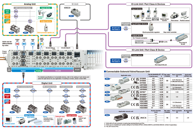
Supports digital inputs/outputs, analog inputs/outputs, and IO-Link units
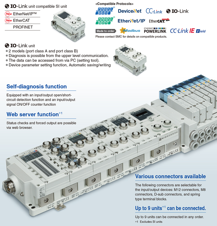
IO-Link
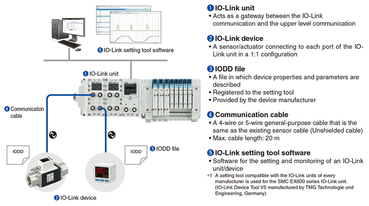
IO-Link is a communication technology for sensors and actuators that is an international standard, IEC 61131-9.
This technology is used to send/receive device information such as manufacturer, product part number, parameters, and diagnostic data, as well as the control data including ON/OFF signals and measured values of the sensor, by connecting the IO-Link master and device in a 1:1 configuration.
IO-Link enables condition monitoring and error detection of the sensor and equipment, and it can contribute to the reduction of startup labor and recovery time and the realization of preventive and predictive maintenance.
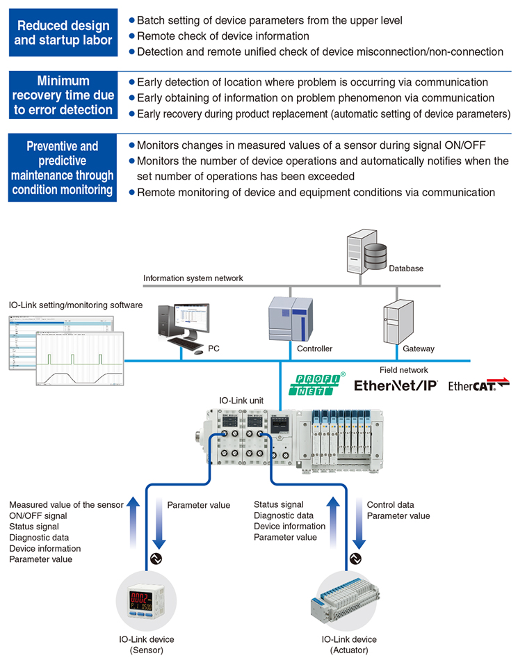
IO-Link System Configuration
IO-Link Interface
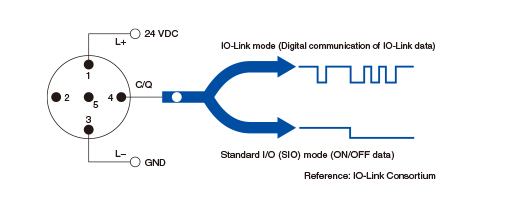
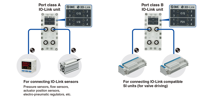
The connecting part between the IO-Link unit and the device is called a “port.” Each port can be switched between “IO-Link mode” for digital communication and “standard I/O mode” for conventional contact input/output.
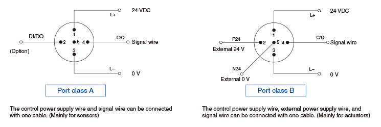
There are two methods for power supply: one is for sensors, and the other is for actuators.
IO-Link Unit
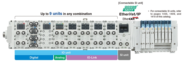
・Can be connected with digital, analog, and IO-Link unit units
Up to 9 IO-Link units can be connected. (36 IO-Link devices can be connected.)
Digital units, analog units, and IO-Link units can be mixed, and up to 9 units can be connected in any order.
・Supports both port class A and port class B
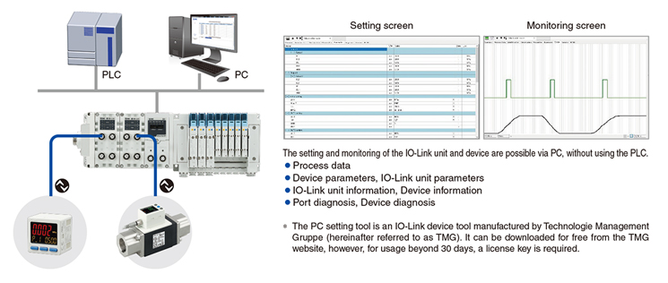
・The data can be accessed from via PC (setting tool).
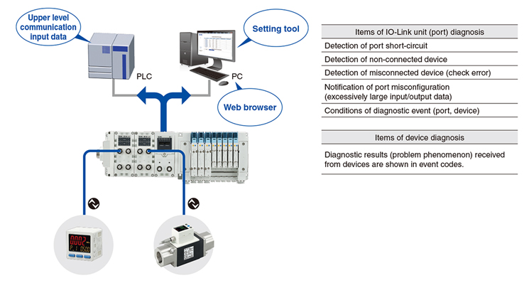
・Diagnosis function
Diagnosis is possible from the upper level communication.
IO-Link unit (port) diagnostic information can be obtained via PLC program or PC (web browser).
Device diagnostic information can be obtained via PC (setting tool).
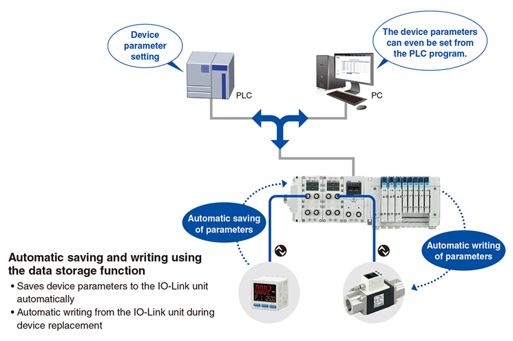
・Device parameter setting function, Automatic saving/writing
The parameter setting of devices is possible from the upper level communication.
Parameter setting is possible via PC (setting tool).
It is also possible to use output data or message data via PLC program.
EtherNet Fieldbus Functions
PROFINET (EX600-SPN3/4), EtherNet/IP™ (EX600-SEN7/8), and EtherCAT (EX600-SEC3/4) support the following functions.
・Compatible topologies (Connection configuration)

・Supports the QuickConnect™ function and the Fast Start Up function

・Built-in web server function
The EX600-SEN7/8, EX600-SPN3/4, and EX600-SEC3/4 have a built-in web server function, which enables status checks,
parameter settings (EX600-SEN7/8 and EX600-SEC3/4), and forced output of the EX600 using general-purpose web browsers,
such as Microsoft Edge.
Start-up of the system and maintenance can be performed efficiently.

PROFINET Technology
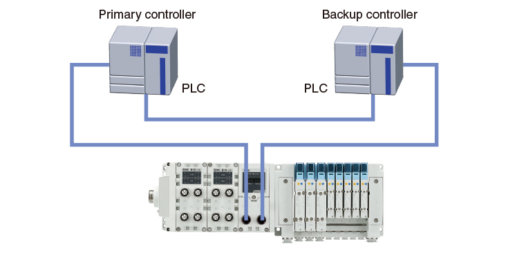
System Redundancy S2
As the EX600-SPN3/4 supports System Redundancy S2, it can continue communication using the backup controller when the primary controller malfunctions. This allows for the prevention of problems caused by unexpected communication interruption.
* In order to use System Redundancy S2, the PLC must be able to support this function.
EX600-SPN31 PROFINET/OPC UA

Fieldbus System EX600

Separate installation possible via a terminal unit New
By using a terminal unit, it is possible to install input devices such as auto switches separately from the valve manifold.

Auto switch failure diagnostic function
By setting the paired input signals of the auto switches mounted on the cylinder to the terminal unit, auto switch failure diagnostics (notification when both auto switches turn ON or OFF simultaneously) is possible. Refer to the connection examples in the“Accessories”section on page 48.


